
Nissan Ecu Wiring Diagram
Bosch ECU pinout diagrams are essential tools for understanding and utilizing wiring diagrams. These diagrams provide detailed information about the connections and functions of the various pins on the ECU, allowing automotive technicians and enthusiasts to diagnose and troubleshoot electrical issues. Identify the Pins: The first step in using.
Car Ecu Wiring Diagram
An electronic control unit (ECU), also known as an electronic control module (ECM), is an embedded system in automotive electronics that controls one or more of the electrical systems or subsystems in a car or other motor vehicle.. Modern vehicles have many ECUs, and these can include some or all of the following: engine control module (ECM), powertrain control module (PCM), transmission.

تشخیص زمان تعویض روغن موتور از طریق اتصال ردیاب خودرو به ECU
In the Automotive industry, the term ECU often refers to an Engine Control Unit (ECU), or an Engine Control Module (ECM). If this unit controls both an engine and a transmission, it is often described as a Powertrain Control Module (PCM). For the purposes of this article, we will discuss the ECU as an Engine Control Unit.
ECU testing and what is a car's ECU? Ask the Car Expert
ECU Circuit Diagram database - download 400 documents : ECU wiring diagram, schematics for cars and info for Bosch EDC16, EDC17, EDC15, ME71, ME75, MED7.. Documentation and car electrical wiring diagrams for EDC17C44. EDC17C44_2-1. EDC17C44 1-1. Wiring schematics and documentation for EDC17C46. EDC17C46 3-1. EDC17C46 2-1.
carecu Kastner Research Group
Basic connection diagrams (PinOuts) of vehicle ECUs, Immobilisers, Instrument Clusters and other automotive Electronic Control Modules. VAG EDC15 PINOUT. VAG ME7xx PINOUT. VAG EDC16 PINOUT. VAG MED9xx PINOUT. VAG SIMOS PPD1x PIN-OUT. VAG IMMO BOXES PINOUTS. VAG EDC17CP04 PINOUT. VAG EDC17CP14, EDC17CP20.
How does a ECU work in a car? ACtronics LTD
Abstract. This report presents a detailed explanation of the Design requirements of Electronic control Unit (ECU) for Engine Management. Due to the regulations demanding lower emissions, together with the need for better performance, fuel economy, continuous diagnosis, Electronic systems form an inevitable part of Engine management.

Car Ecu Circuit Diagram
Wiring diagram still image: https://drive.google.com/file/d/1DKel__bDe8tx9m7dXXaRK01CHTybJ6cG/view?usp=sharingWiring diagram editable: https://drive.google.c.

ECU Engine Control Unit
An ECU wiring diagram is a graphical representation of the electrical system in a vehicle. It typically includes components such as sensors, switches, relays, and connectors, and shows how they are connected. The diagram can be used to determine where a fault is located in the electrical system and can be used to trace the power flow throughout.

How Ecu Works Diagram
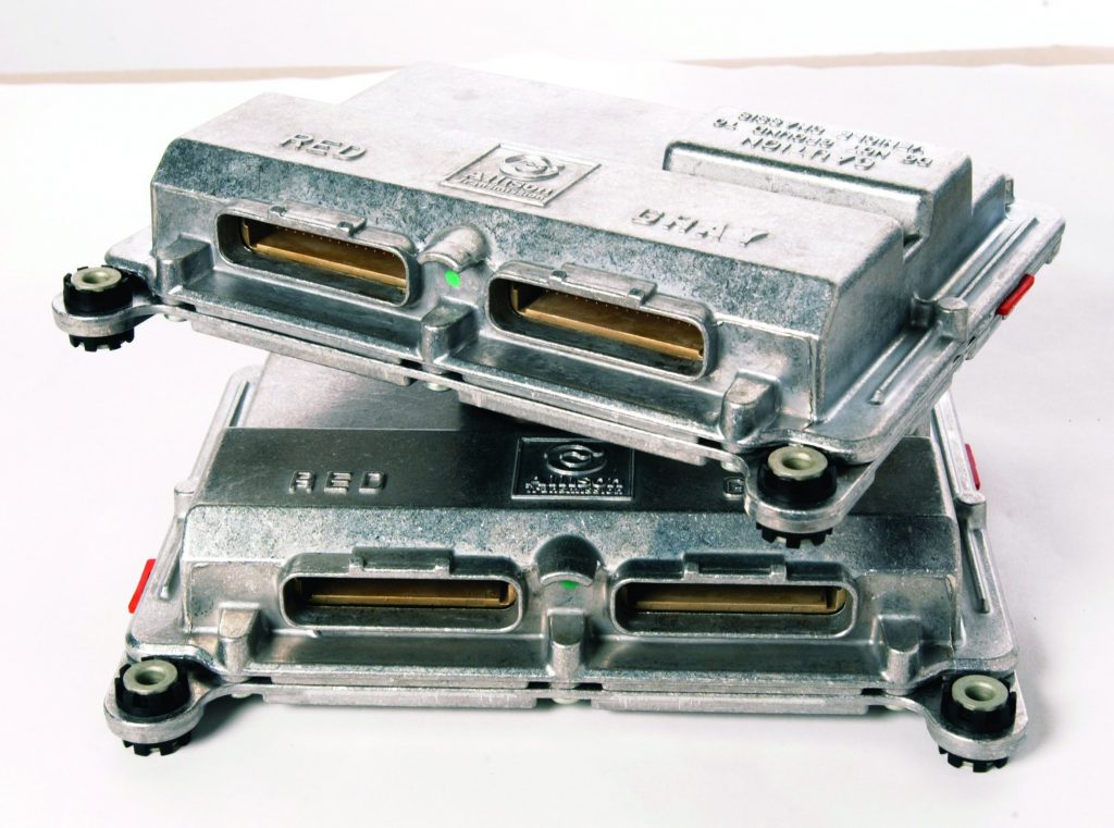
Delco ECU used in General Motors vehicles built in 1996. An engine control unit (ECU), also called an engine control module (ECM), is a device which controls multiple systems of an internal combustion engine in a single unit. Systems commonly controlled by an ECU include the fuel injection and ignition systems.. The earliest ECUs (used by aircraft engines in the late 1930s) were mechanical.

Nissan ecu pinout diagram Nissan, Car ecu, Ecu
Constant database expansion and system improvement. New data categories, user demand analysis, usability improvements. Round-the-clock availability. Available 24 hours a day, regular online updates. MotorData is an interactive information and reference data system on automotive diagnostics and repair: wiring diagrams, DTC, ECU pinout, TSB,.
Suzuki Jimny Ecu Wiring Diagram
A Car ECU Circuit Diagram PDF can be a valuable asset in any garage or workshop, helping to diagnose, troubleshoot, and prevent issues related to your car's engine. Mazda Car Pdf Manual Wiring Diagram Fault Codes Dtc. Eaton Cur Style Wiring Harness Autoselect. Wiring Schematics And Diagrams Triumph Spitfire Gt6 Herald. I Have A Toyota Carina.

Car Ecu Block Diagram
How To ask for your vehicle wiring diagrams. Auto Electrician Hayes Ltd, Greater London, United Kingdom, offers DIY lovers Free Car Wiring Diagrams. Free ECU Pin-Out to help you repair your cars' electrical problem. Free car repair help and guide for Mercedes, BMW, VW, Audi, Skoda, Seat, Porsche, Toyota, Suzuki and Honda.
Car Ecu Circuit Diagram
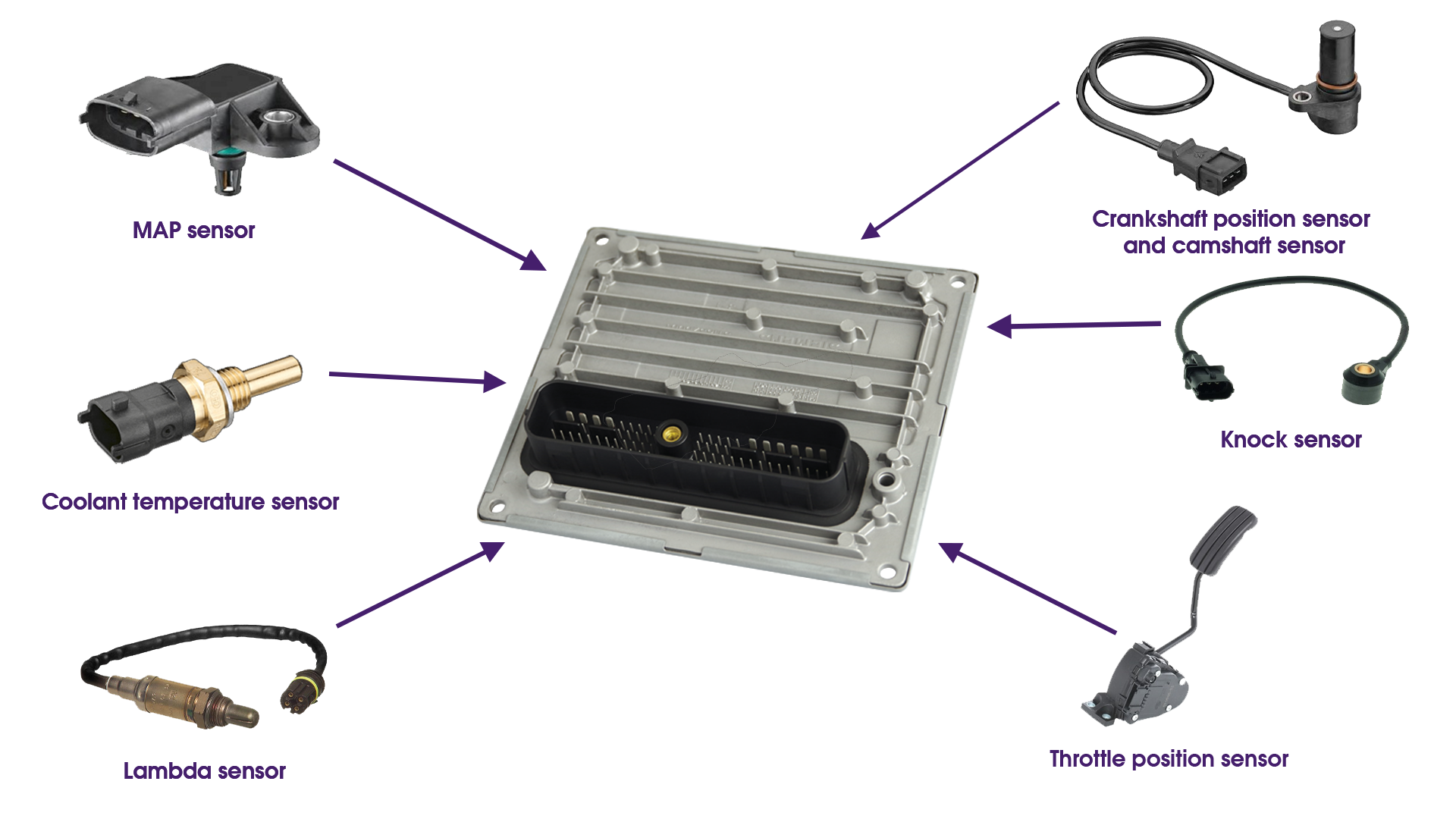
Outputs from the ECU: - Fuel injectors to deliver fuel to the engine. - Ignition coils to generate the spark needed to ignite the fuel mixture. - Idle air control (IAC) valve to control the amount of air entering the engine at idle. - Variable valve timing (VVT) system to adjust the timing of the intake and exhaust valves for optimal performance.
Car ECU Know the Functions, Types, and Characteristics of the Damage
Figure 1 is a simple wiring diagram showing a fog lighting circuit. The circuit consists of a battery, 20A fuse (used to protect the circuit), a switch (located on a dash panel), and two fog lights. Ground returns are shown by the ground symbol of a vertical line with three horizontal lines.

Color ECU Pinout Diagrams 4 Door Sports Cars, Car Ecu, Engine Control
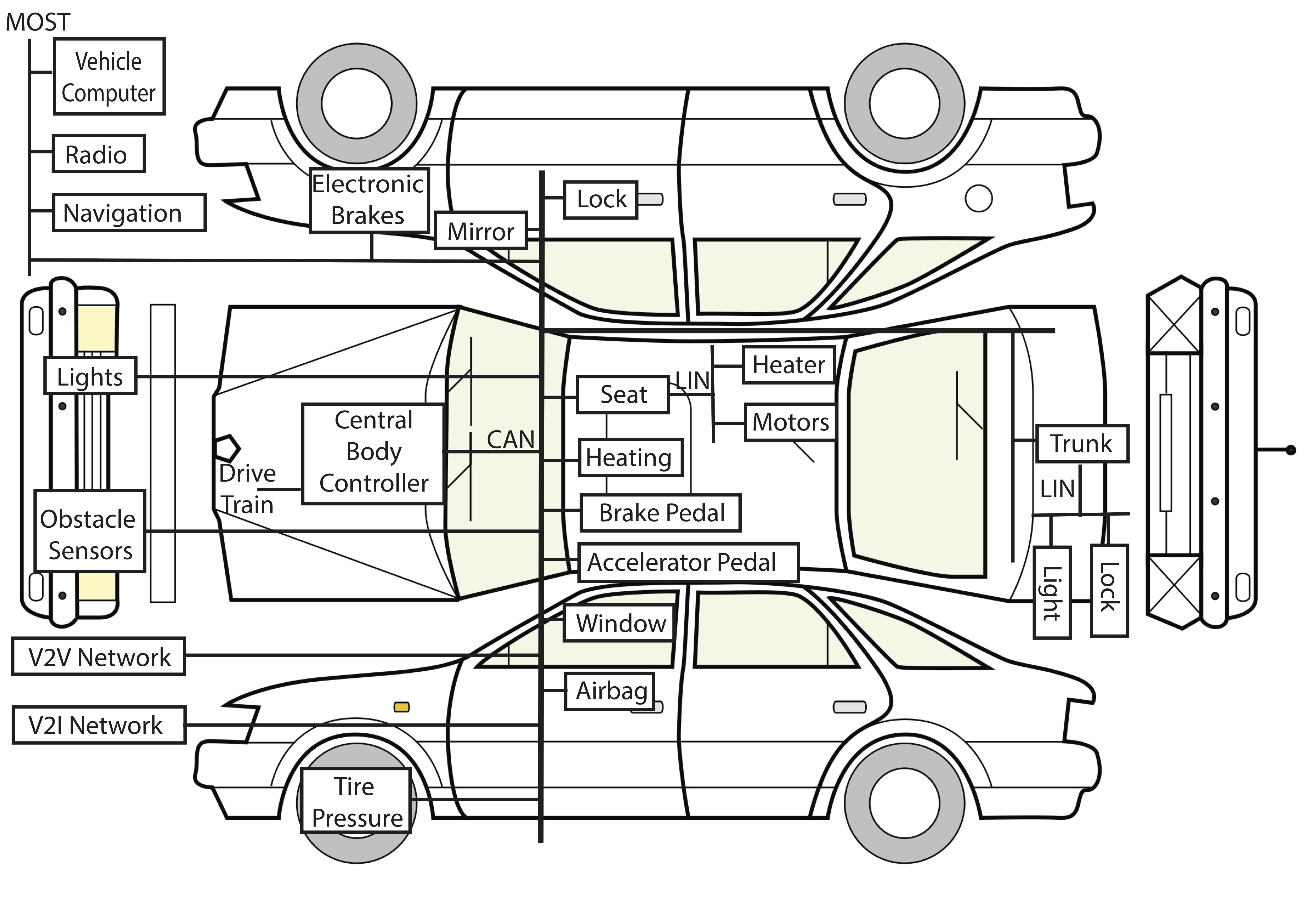
An electronic control unit (ECU) is a small device in a vehicle's body that is responsible for controlling a specific function. Today's vehicles may contain 100 ECUs or more, controlling functions that range from the essential (such as engine and power steering control) to comfort (such as power windows, seats and HVAC), to security and access (such as door locks and keyless entry). ECUs.

toyota 5afe ecu wiring diagram
Some of the other components in the ECU that support the processor are: Analog-to-digital converters - These devices read the outputs of some of the sensors in the car, such as the oxygen sensor. The output of an oxygen sensor is an analog voltage, usually between 0 and 1.1 volts (V). The processor only understands digital numbers, so the.